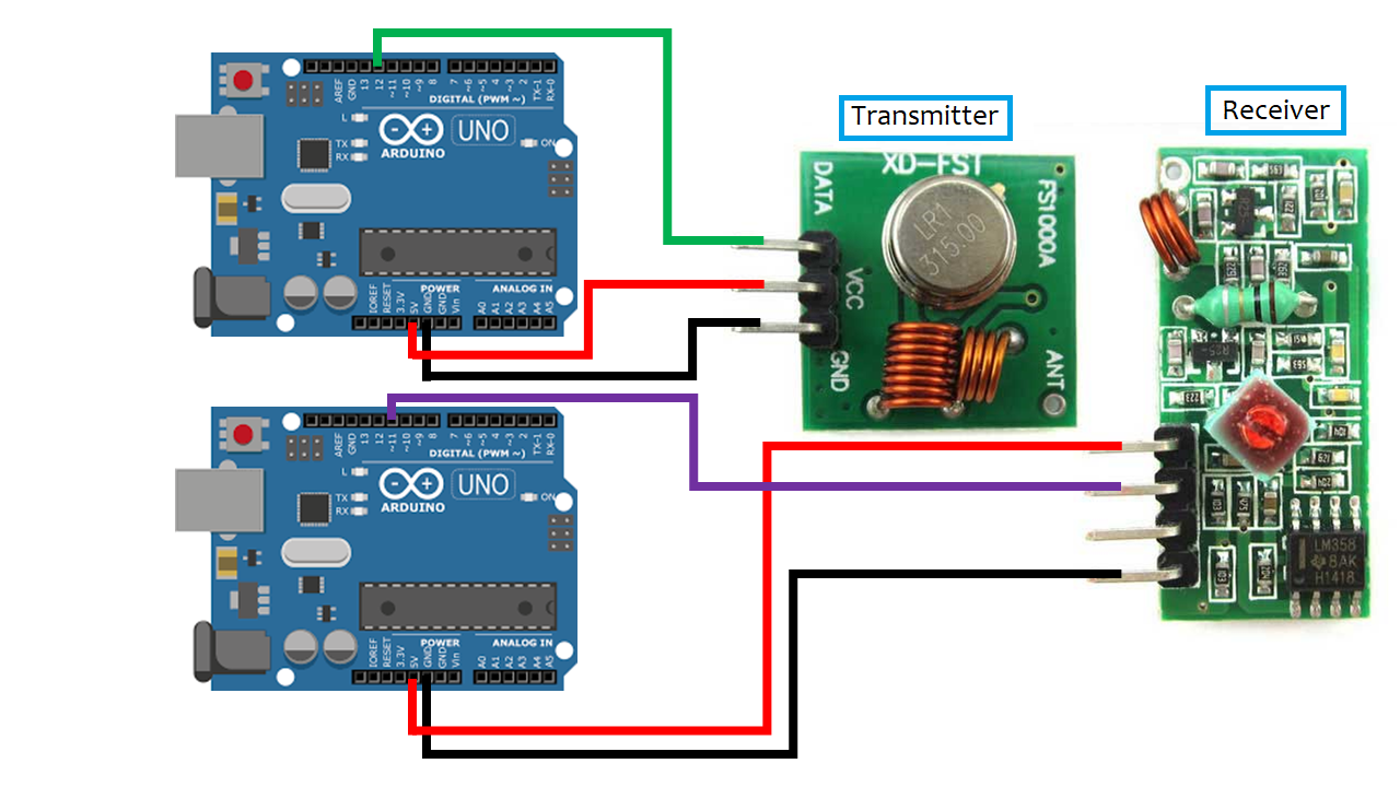
The 433MHz RF Transmitter/Receiver modules can be used to transmit an array of numbers or characters wirelessly between Arduinos. The original Arduino code by Random Nerd Tutorials was adapted for the rover to receive a 12-character string from the transmitter containing embedded numbers. The Receiver interprets the message by separating the numbers and converting it into a command. The code for this can be found on Mission 1 page.
The RF Receiver will be mounted on the rover allowing for communication of the intended target's location. The RF transmitter with send both a distance command and GPS coordinates of the target location. The rover will receive these commands wirelessly and determine its route.
2 - Arduino Uno
1 - 433 Mhz Radio Frequency Transmitter FS1000A
1 - 433 Mhz Radio Frequency Receiver RF-5V
6 - Arduino Solderless Female to Male Jumper Wires
1. Attach the RF receiver and transmitter to separate Arduinos. Both can be programed with the same
computer but the transmitter must stay connected for the serial monitor and user input. In order to
see the message from the receiver it must be connected separate from the transmitter with its own
serial monitor.
2. Download and insert the RadioHead Library into the provided sketch. If the driver isn't properly
installed the program will not work.
3. Insert the SPI library from the insert library drop-down menu within the program. This library
is used for compiling the program. If not present the sketch will not run.
4. Upload the appropriate sketch to each Arduino (the transmitter is the smaller component). The
message from the transmitter can be seen on the receiver monitor.

HC - SR04 Ultrasonic distance measuring module is capable of detecting objects up to 400 centimeters away. The module uses high frequency sound waves to determine the distance between the module and an object. The Arduino code is from DroneBot Workshop.
The Ultrasonic module will aid the ASA rover in obstacle avoidance. This effectively gives the rover its eyes allowing it to sense upcoming objects and initiate an avoidance algorithm. The module will also be used to determine if an obstacle is small enough for the rover to crawl over or go around.
1 - Arduino Uno
1 - HC-SR04 Ultrasonic Sensor
4 - Arduino Solder-less Female to Male Jumper Wires
There is no library needed for the Ultrasonic Range Finder. Simply upload the provided sketch to the Arduino and open the serial monitor. Place the module perpendicular to a flat surface and it will display the distance on the monitor.

Adafruit Ultimate GPS Breakout module has 66 channels with 10 Hz update speed and external antenna. The module gives readings on current location in latitude and longitude. The program will interpret current coordinates from the GPS module and calculate the distance to a target location given the target coordinates. A basic example can be found by GitHub. The commands in the Arduino code came from this example.
The ASA Rover will use this GPS module to navigate to specific way points and also use it for accurate compass headings. To navigate to specific GPS coordinates the rover must first receive its current location and then calculate the direction and distance to its intended target. Using the rover's longitude and latitude points as it moves, the rover can also determine which compass heading it is currently on.
1 - Arduino Mega
1 - AdaFruit! Ultimate GPS Breakout v3 with Antenna
4 - Arduino Solderless Female to Male Jumper Wires
1. Assemble the Arduino Mega and the GPS module according to the schematic.
2. Download the "TinyGPSPlus" library.
3. Insert the provided code into a sketch and insert the library.
4. Upload the sketch onto the Arduino Mega.
5. Place the antenna out-of-doors.
6. Open the serial monitor and wait for your first GPS fix.
The GPS module is sensitive to weather conditions and large structures. Avoid cloudy days and using inside buildings.

The Master/Slave Arduino tutorial demonstrates the ability to use multiple Arduino micro-controllers to control external hardware when memory space is limited or libraries conflict in one sketch. This becomes very important during Mission 4 because the RF receiver and the servo libraries interfere with each other making it impossible to control both from the same Arduino. It is possible to write a custom library to fix the issue but who has time for that? The easiest solution is to have a Master Arduino run the majority of the code and send commands to the Slave Arduino to run simple functions.
The Master Arduino was programmed to send digital pulses to the Slave for different commands. The Slave responds to the pulses and lights LED corresponding to the specific pin it received the pulse.
2 - Arduinos (Uno or Mega)
1 - Solder-less Breadboard
7 - Arduino Solderless Female to Male Jumper Wires
3 - LEDs
1. Run three jumper wires from the Master Arduino to the Slave Arduino pins.
2. Connect a jumper wire from the ground of one Arduino to the other.
3. Run three more jumper wires from the Slave Arduino output pins to the bread board.
4. Wire the LEDs to each jumper wire with a 330 ohm resister in series to ground.
5. Upload the appropriate code to both the Master and Slave Arduinos.
The Arduinos and the LEDs must all be grounded to each other. For trouble shooting, make sure the pulse pins on the Master Arduino correspond to the receive pins on the Slave both physically and in the code.