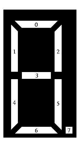
Pseudo-drive an LED display.
A standard digital LED display is N blocks (digits) of the device in the figure. There are eight wires tied to the microcontroller for each of the eight led segments in the block. You are to write the conversion of decimal numbers to a format suitable for driving such a display.
The convention for an LED driver is to write a logical 1 when the corresponding segment is off, and to write a 0 when the segment is on.
The basic digit formats corresponding to the segment labels in the figure are as follows:
Digit | Segment | Hex | |||||||
7 | 6 | 5 | 4 | 3 | 2 | 1 | 0 | ||
0 | 1 | 0 | 0 | 0 | 1 | 0 | 0 | 0 | 0x88 |
1 | 1 | 1 | 0 | 1 | 1 | 0 | 1 | 1 | 0xDB |
2 | 1 | 0 | 1 | 0 | 0 | 0 | 1 | 0 | 0xA2 |
3 | 1 | 0 | 0 | 1 | 0 | 0 | 1 | 0 | 0x92 |
4 | 1 | 1 | 0 | 1 | 0 | 0 | 0 | 1 | 0xD1 |
5 | 1 | 0 | 0 | 1 | 0 | 1 | 0 | 0 | 0x94 |
6 | 1 | 0 | 0 | 0 | 0 | 1 | 0 | 0 | 0x84 |
7 | 1 | 1 | 0 | 1 | 1 | 0 | 1 | 0 | 0xDA |
8 | 1 | 0 | 0 | 0 | 0 | 0 | 0 | 0 | 0x80 |
9 | 1 | 1 | 0 | 1 | 0 | 0 | 0 | 0 | 0xD0 |
In this problem, you are to generate the byte values to be written to an led display driver to display decimal numbers in various fixed point formats.
The input file will contain a sequence of decimal formatting problems. These will be written as three comma-separated numbers on a line:
An example input file would be:
column 1111111111222222222233333333334 1234567890123456789012345678901234567890 line 1:8,0,0.15707963267948966192313216916398[EOL] 2:8,1,0.15707963267948966192313216916398[EOL] 3:8,2,0.15707963267948966192313216916398[EOL] 4:8,3,0.15707963267948966192313216916398[EOL] 5:8,0,1.5707963267948966192313216916398[EOL] 6:8,1,1.5707963267948966192313216916398[EOL] 7:8,2,1.5707963267948966192313216916398[EOL] 8:8,3,1.5707963267948966192313216916398[EOL] 9:8,4,1.5707963267948966192313216916398[EOL] 10:8,5,1.5707963267948966192313216916398[EOL] 11:8,6,1.5707963267948966192313216916398[EOL] 12:8,7,1.5707963267948966192313216916398[EOL] 13:8,1,15.707963267948966192313216916398[EOL] 14:8,1,157.07963267948966192313216916398[EOL] 15:8,1,1570.7963267948966192313216916398[EOL] 16:8,1,15707.963267948966192313216916398[EOL] 17:8,1,157079.63267948966192313216916398[EOL] 18:8,1,1570796.3267948966192313216916398[EOL] 19:8,1,15707963.267948966192313216916398[EOL] 20:1,0,0[EOL] 21:1,0,1[EOL] 22:1,0,2[EOL] 23:1,0,3[EOL] 24:1,0,4[EOL] 25:1,0,5[EOL] 26:1,0,6[EOL] 27:1,0,7[EOL] 28:1,0,8[EOL] 29:1,0,9[EOL] :[EOF]
Here are the general display rules:
Other than the standard leader an trailer, the output file simply has the bytes to be written to the display driver in hexadecimal format.
The correct output corresponding to the example input file would be
column 111111111122222222223 123456789012345678901234567890 line 1:Program 5 by team 0[EOL] 2:FF FF FF FF FF FF FF 08[EOL] 3:FF FF FF FF FF FF 08 A2[EOL] 4:FF FF FF FF FF 08 DB 84[EOL] 5:FF FF FF FF 08 DB 94 DA[EOL] 6:FF FF FF FF FF FF FF 22[EOL] 7:FF FF FF FF FF FF 5B 84[EOL] 8:FF FF FF FF FF 5B 94 DA[EOL] 9:FF FF FF FF 5B 94 DA DB[EOL] 10:FF FF FF 5B 94 DA 88 80[EOL] 11:FF FF 5B 94 DA 88 80 88[EOL] 12:FF 5B 94 DA 88 DA D0 84[EOL] 13:5B 94 DA 88 DA D0 84 92[EOL] 14:FF FF FF FF FF DB 14 DA[EOL] 15:FF FF FF FF DB 94 5A DB[EOL] 16:FF FF FF DB 94 DA 08 80[EOL] 17:FF FF DB 94 DA 88 00 88[EOL] 18:FF DB 94 DA 88 DA 50 84[EOL] 19:DB 94 DA 88 DA D0 04 92[EOL] 20:DB 94 DA 88 DA D0 84 12[EOL] 21:08[EOL] 22:5B[EOL] 23:22[EOL] 24:12[EOL] 25:51[EOL] 26:14[EOL] 27:04[EOL] 28:5A[EOL] 29:00[EOL] 30:50[EOL] 31:End of program 5 by team 0[EOL] :[EOF]